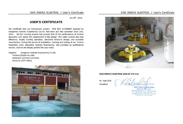
Hydrotu a exécuté toutes les responsabilités. Le groupe électrogène de turbine et de l'eau fonctionne sans risque et solidement avec la qualité bruyante et bonne inférieure.
—— HUlUSI SITKI - La Turquie
La turbine achetée du hydrotu en 2010, il fonctionne solidement, travail continu sans défauts, a le service après-vente parfait.
—— Dragan Klisura-Serbie
Je suis en ligne une discussion en ligne
Société Le blog
what's the Bulb Tubular Turbine Generator structure?low water head hydropower project.
Tubular turbines / Part 3
Bulb Tubular Turbine Generator
The third member of the tubular family does away with the shaft, the bend and the machine hall: the generator travels inside the water passage, and everything — bulb nose to draft tube — sits on one straight axis.
Two members of the tubular family have already been described in this series — the shaft-extension tubular unit and the pit tubular unit. This article deals with the third: the bulb tubular turbine generator set.
The bulb unit is made up of embedded parts, the generator, the distributor, the main shaft, the bearings, the runner and the concrete structures. Every working component lies on one and the same axis, which is what makes it a horizontal-shaft machine.
7.9 mrunner diameter, Jirau — the largest bulb runner built
75 MWlargest single-unit rating in service (22 units, left bank)
57 MWlargest unit in China — Qiaogong, in service since 2009
1The generator
The generator inside a bulb unit is close in construction to an ordinary hydro-generator, and that machine is covered in detail elsewhere on this site, so only the arrangement matters here. Fig. 1 shows the stator and the rotor of a bulb generator.
Fig. 1 — Stator and rotor of a bulb tubular generator. The rotor is a salient-pole assembly on a spider; the stator core and winding sit in a frame split into halves for assembly inside the bulb.
The rotor is mounted on the rotor flange of the main shaft. The stator is mounted inside the stator frame, and the stator frame is bolted to the front face of the inner shell of the tubular casing. That single sentence fixes the whole assembly sequence of the machine: the shaft hangs off the rotor flange, and the stator hangs off the casing.
2The tubular casing
The tubular casing — also called the stay ring — consists of an inner shell, an outer shell, an upper shaft and a lower shaft (Fig. 2). The front face of the inner shell carries two concentric rings of tapped holes. The outer ring takes the stator frame, which is mounted directly on that face; the inner ring takes the support ring, the base that fixes the thrust and guide bearing. On the rear face of the inner shell, a further ring of holes takes the inner distributor ring; around the rear edge of the outer shell, another ring takes the outer distributor ring. The shafts through the casing are the access route by which maintenance staff enter the bulb.
Fig. 2 — Where the casing sits in the assembly. With the shell cut away, the stator frame can be seen seated on the front face of the inner shell, and the upper and lower shafts passing through the casing as the access route into the bulb.
The tubular casing is the mounting datum for the entire unit. It is embedded in the concrete foundation as the concrete is placed, and before placing, its axis, level, plumb and position must be held to strict tolerance — the installation accuracy of the whole machine follows from it. Get the casing wrong and nothing downstream can be corrected.
3The distributor
Like the shaft-extension and pit types, the bulb unit uses a conical distributor. The guide vanes are mounted between the outer distributor ring and the inner distributor ring. Each vane stem is connected through a lever and a connecting rod to the control ring, and a servomotor pushes the control ring round. Because the ring is a full circle and the servomotor is a single straight cylinder, the servomotor pushes tangentially — a pull rod on one side of the ring is enough to rotate every vane at once.
Fig. 3 — The distributor seen from two directions. Left: looking upstream into the vanes, between the two distributor rings. Right: the same assembly from the side, showing the lever and connecting-rod linkage around the outside of the control ring.
Fig. 4 shows the two end positions of the same mechanism: guide vanes open on the left, guide vanes closed on the right. The working principle — how the servomotor stroke is turned into vane angle — is the same as for any turbine distributor, and is treated separately.
Fig. 4 — The two end positions of the distributor. One servomotor stroke rotates the control ring, the ring swings every lever through the same angle, and every vane turns with it — open at full stroke one way, closed at full stroke the other.
4The shaft train
The runner consists of a runner body and blades, and works on the same principle as any axial-flow turbine. The runner drives the generator rotor through the main shaft: the generator rotor is mounted on the rotor flange at the front end of the shaft, and the runner on the flange at the rear end.
Fig. 5 — The main parts distributed along the shaft (generator rotor omitted). From the upstream end: oil receiver and slip rings, the combined thrust and guide bearing on its support ring, the main shaft, the runner-side guide bearing, the shaft seal, and the runner.
At the front end of the shaft sits the combined thrust and guide bearing. In normal operation a tubular turbine carries the forward thrust of the water, but during shutdown it is subject to a reverse impact, so the thrust bearing is made double-acting. The guide bearing carries the weight of the generator rotor and the radial unbalance produced as it turns. The combined bearing is mounted through the support ring on the front face of the inner shell.
At the rear end of the shaft there is a runner-side guide bearing, which carries the weight of the runner and its radial forces; it is housed inside the discharge cone at the tail of the bulb nose. Between the tail of the discharge cone and the front face of the runner mounting flange is the shaft seal, which keeps water out of the bulb.
Control oil reaches the blade mechanism through the oil receiver, which feeds oil into a pipe inside the main shaft and so to the hydraulic gear in the runner that changes blade angle. The oil receiver is at the extreme front of the shaft; beside it are the slip rings, which carry excitation current to the generator rotor. Both are therefore reachable from the front of the bulb, without dismantling the machine.
Everything the machine needs to be controlled — excitation, blade angle, bearing thrust — enters through the upstream nose of the bulb. The downstream end is nothing but the runner and water.
5Construction of the unit
The generator of a bulb unit is enclosed in a steel shell shaped like a light bulb. Water flows around the outside of the bulb and on to the runner at its tail, driving the runner round. Fig. 6 is a section through a model of the unit.
Fig. 6 — Section through a model of the bulb unit. The bulb is built in five bolted segments; upstream of the tubular casing the water passage is concrete, downstream of it the passage is steel.
The bulb of the model is built in five segments — bulb nose, generator frame, tubular casing, inner distributor ring and discharge cone — bolted together at the joints. The upstream part of the water passage is concrete; from the tubular casing downstream the passage is steel, in the form of the outer distributor ring, the runner chamber and the draft tube.
Above the inlet passage is the generator pit, through which the generator, the bulb nose and other equipment are lowered into place. Once installation is complete, the pit opening is closed with a pressure cover plate. The distributor, the runner and similar parts are installed through the turbine pit instead. Fig. 7 shows the same unit with the shell cut away to reveal the internal structure.
Fig. 7 — The unit cut open. Stator and rotor in the bulb, the shaft running through the tubular casing, the distributor ring of guide vanes, and the runner in its chamber ahead of the draft tube.
One further view, from behind and to one side, is worth having: it is the view a site engineer actually gets when the unit is being assembled, looking upstream into the runner chamber with the draft tube cone cut back.
Fig. 8 — The same assembly from behind and to one side. The runner and its blades sit in the runner chamber; the draft tube opens out downstream of it, and the control ring and servomotor hang on the outside of the distributor.
6Why the type is growing
With the medium- and high-head hydro sites in China now largely developed, most of the remaining resource is low head. The bulb unit — compact, stable in operation and comparatively efficient — is the machine for low-head, medium-to-large stations, and it has developed quickly in recent years as unit ratings have risen.
In China the largest bulb unit is Qiaogong, in service since 2009, with a unit capacity of 57 MW. Abroad, the Jirau station built in Brazil had all 22 units of its left bank in service by 2016; those units were designed and built in China, rated 75 MW each with a 7.9 m runner diameter — the largest in the world.
The bulb unit can also run in reverse, which suits tidal stations and gives two-way generation. Because only forward flow passes through the distributor, and the blades are cambered for best forward performance, efficiency in the forward direction is high — above 90% — while in reverse flow it falls below 90%.
The unit can equally be run as a pump, with two-way pumping, which makes it well suited to low-head pumping stations; it is used on the eastern route of the South-to-North Water Diversion project. Purpose-built pump sets of this kind have no distributor at all.
The type at a glance
Shaft arrangement
Horizontal, all working parts on a single axis
Generator position
Inside a steel bulb in the water passage, upstream of the runner
Distributor
Conical; guide vanes between inner and outer distributor rings
Thrust bearing
Double-acting — forward thrust in operation, reverse impact at shutdown
Low head, large flow; medium-to-large stations, tidal and pumping schemes
About the figures. All eight drawings are labelled bilingually — Chinese above, English below — so they can be read against the original terminology. Colour is used consistently across the set: green for the bulb shell, blue for the casing and distributor body, gold for the control ring and linkage, red for the generator rotor.


 Votre message doit contenir entre 20 et 3 000 caractères!
 French